
Tiny Tank
I dusted off a kit tank I've had laying around for a decade (+/-).
I built the project I would have always liked to, but this time with a Raspberry Pi Zero W. I salvaged almost all of the hardware (chassis, motor controller, motors) and had an analog infrared distance sensor. I connected everything as nicely as I possibly could, with connectors and protoboards. Here's my quest.
Salvage Phase
I just pulled everything off of the old project for this step.
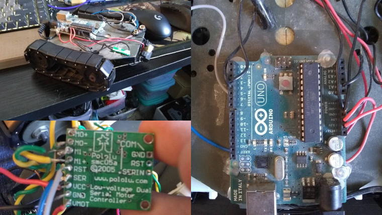
I pulled off an Arduino Uno, a bunch of hot glue, and desoldered some truly revolting novice solder joints.
Motor Control
The motor controller takes V_mot (6 volts) and safely varies the speed and direction with serial commands over logic voltage (3.3 volts).
I also put my new crimpers to use, and mixed JST and Dupont connectors to make everything somewhat modular. The motors shouldn't need to be disconnected ever again, but it's better than needing to desolder if I ever tinker with this section again.
Motor Schematic
I started here because it's pretty simple: just connect the wires to the right place. I need 4 wires to control this section: VCC, GND, SER (serial), and RST (Reset). When reset isn't held high, the motor controller should stop immediately, causing the robot to stop in the event of a Raspberry Pi crash / reboot.
The only deviations from this "straight through" schematic concept are:
- a pull-down resistor for the
RSTline. I attempted to also run this through a hardware switch, so I could hardware OR software safe this robot. In practice, I couldn't get this to work and took my chances with a robot that could bolt away from me at a velocity of tens of feet per minute. - A switch to completely disconnect
V_motwhich makes the robot safe and convenient to send test commands to: the motor controller will light up the forward and reverse LEDs, but the motors can't be powered through the 3.3V logic.

(Serial / ground wires omitted from schematic - just more straight lines)
Motor Breakout Protoboard
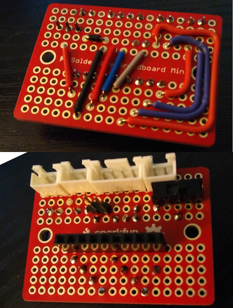
I used a "Solderable Breadboard" for this simple circuit, which cuts down on wires by copying the internal layout of a breadboard. I decided to use the middle divider of the "breadboard" to separate the input side (from the Raspberry Pi + motor controller) to the output side (motors, battery hookups).
Mounting
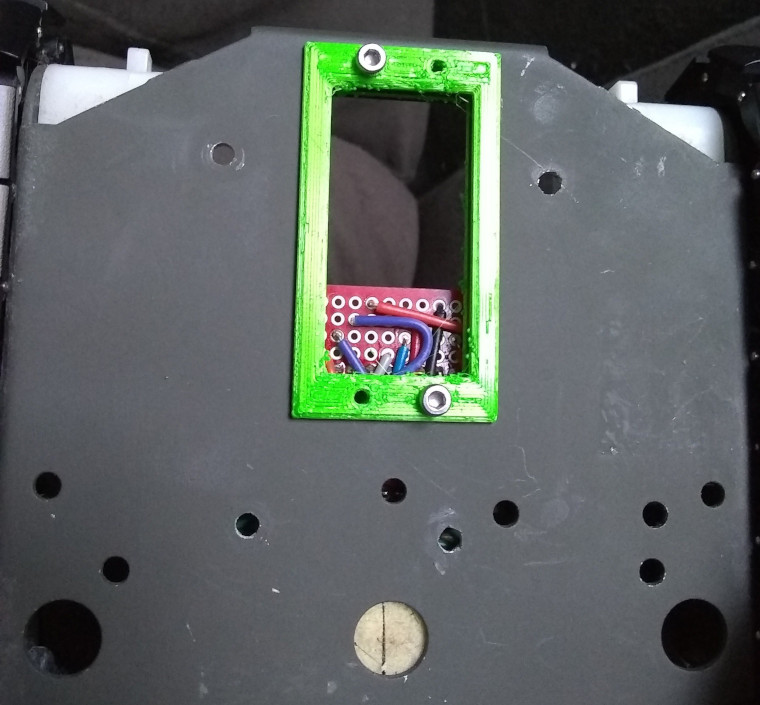
3D printed mounts allow me to match up the bolt holes on the chassis with the bolt holes on the circuit board. I used green plastic (whatever was loaded at the time) as the test fit.
Since the Raspberry Pi and the sensor circuits are going to be mounted on top, I made a quick top mount hold the motor controller on the bottom.

Analog Infrared Sensor
This is a somewhat older style of IR sensor that has three pins: VCC (5V), GND, and A_out.
Big Problem Time
This sensor provides an analog output: a voltage between 0.3 and 3.0 volts, representing the distance detected.

(From the Sharp GP2D120 documentation)
The Raspberry Pi, unlike the common Arduino, has no analog inputs. It doesn't have an ADC to provide. Just to have a bit more fun, I'm going to make this the hard way, and do more of the problem solving in software.
My solution was to make a Successive Approximation Analog-to-Digital Converter using a digital potentiometer (in a voltage divider) and a comparator.
Soft-ADC
Step 1, control a reference voltage. I used a X9C104 digital potentiometer: it was available in a through-hole breakout on Amazon, and has a hundred 1k steps of resistance. It's not as hardy as a real resistor (only rated up to 5V), but that's fine since I'm using it to crank 3.3V down to a voltage between 0.3 and 3.0.

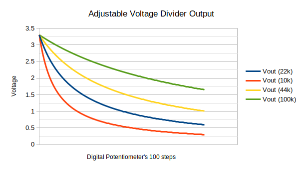
I played with the resistor values I had on hand and a spreadsheet and then did some tests on a breadboard. What the datasheet says and what my sensor actually output in reality were somewhat different; I ended up on a 22k permanent resistor to make up the other side of my voltage divider.
Step 2, compare. The analog output of the IR sensor is useless for the Raspberry Pi, but a comparator can tell us in perfectly digital TRUE or FALSE terms if the reference voltage (which we can control) is larger or smaller than the current analog value.
When the digital potentiometer is cranked down to 0, the full 3.3V value comes through; when it's on 100, only about 0.5V comes through. It's important to match the useful range, because I only have 100 steps of resistance. If I have resistance values the sensor can never output, then I'd be allocating limited, quantized inputs that can never be produced.
For example, with a permanent resistor of 10k in my voltage divider, step 0 equates to 0.3 volts - fits the datasheet perfectly. However, 0.5 volts comes around step 10, and if the sensor almost never goes below that value, then I only have 90 steps that would be actually detected in practice.
Step 3, sweep. The Soft-ADC can now adjust the resistance up and down and observe when the comparator flips from high to low or vice versa. This means I can constantly adjust my digital potentiometer, tracking which tap, and therefore which voltage is comparable to the analog input at this moment.
As a result, I constantly have two values: the high and low tap. In an ideal setting, these taps are adjacent, i.e. at step #50 the comparator is low, and at step #51 it's high.
This is what successive approximation means - taking multiple steps to narrow down the range of results. I could use a binary search instead of checking after each individual value to make this fancier, but with just 100 steps I don't think the speedup could be very significant; in fact, the digital potentiometer can only be incremented or decremented, so a binary search would be more operations and overshoot its target a few times while searching.
Step 4, process. I'm not currently getting all of the meaning out of this data. Also, I could probably switch through digital potentiometer levels or observe the comparator faster. I'll give it a try and see what I can come up with.
Final Considerations on the Soft-ADC
For the time being, though, there's a non-instantaneous amount of time elapsed between changing levels on the comparator. While I'm adjusting the reference voltage, objects may be in motion. This can cause a wide gap of 5 or 10 steps between the high and low levels.
Considerations like these are why I imagine analog to digital converters are kind of slow: AnalogRead() on Arduino is far from instantaneous. On Raspberry Pi, I have the added confusion of not knowing precisely how the OS is scheduling my program's cycles. I'm having a good time looking under the hood, though.
I definitely used several more GPIO pins here than is necessary to solve the problem, but I avoided the pins for interesting buses like I2C; Only boring old digital IO is used. I don't think this lack of parsimony would block me from expanding the robot's capabilities in the future.
I'm happy with the extra detail this method provides me. I think average, min, and max values all have their uses for sensor value interpretation.
Pi Shield
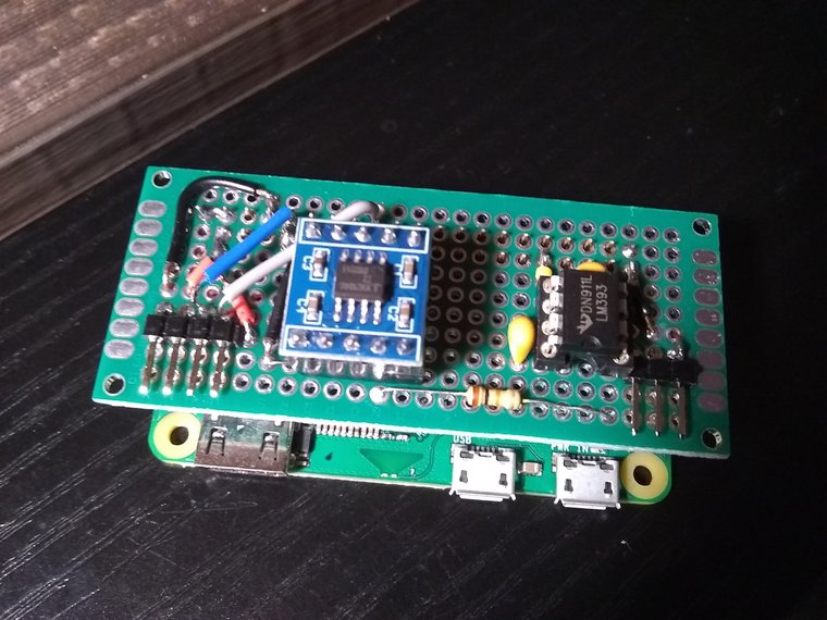
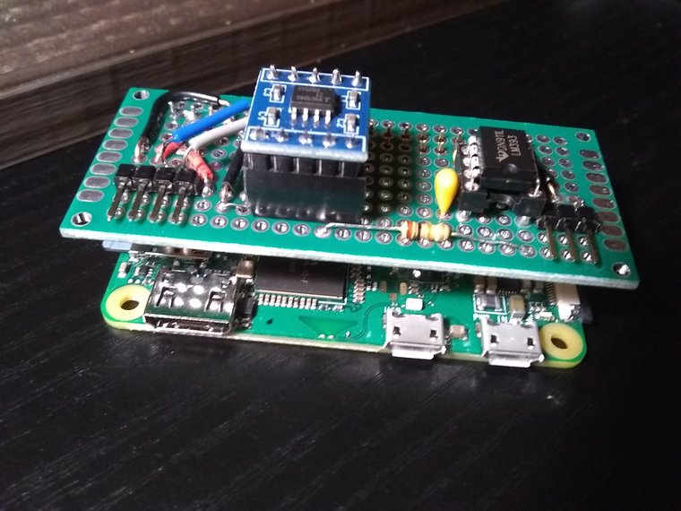
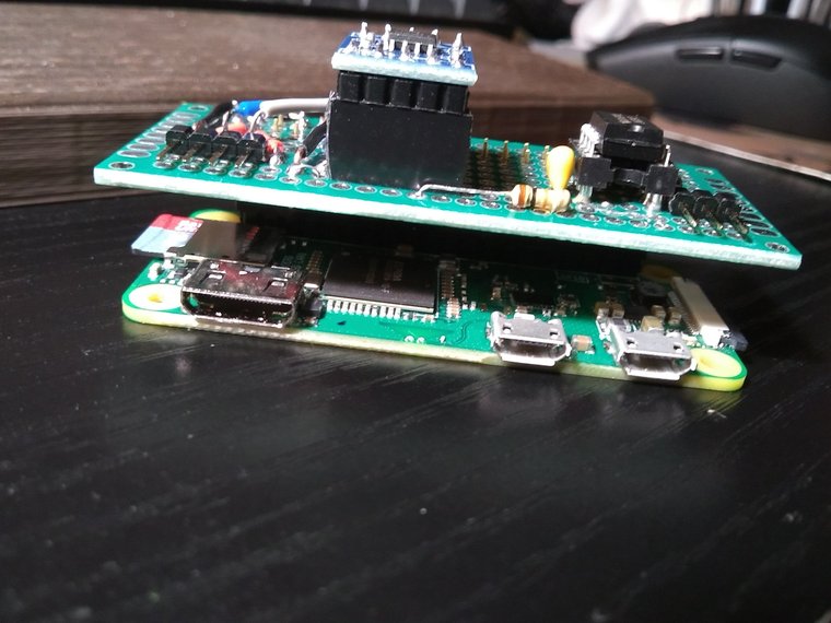
What's a Shield? It's a board that extends another board. Typically they have the same size and shape and their pins match up. In this case, the shield will have the input processing circuit, containing:
- The digital potentiometer
- the comparator
- the input connector for the analog distance sensor
- as a convenience, also the connector for the motor controller.
Schematic

The CS, UD, and INC lines control the digital potentiometer (3 digital outputs); there's one digital input to get the comparator's status. A total of 4 wires with no high-level communication protocol to replace an Analog to Digital Converter.
Breadboard

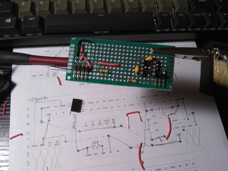
Protoboard Layout
The protoboard I'm showing here is actually my second attempt. I made a protoboard with very little planning (Just copy the breadboard, right??) and it was impossible to troubleshoot. Only with a very detailed plan in hand was I able to test my circuits and get everything working. So my advice is to figure out your layout before making a protoboard at all...

A protoboard is a grid. I used a spreadsheet with all the cell borders turned on, but graph paper would work too. I printed a couple copies of the layout and drew separate layouts for power and various signals. I arranged stuff on the protoboard so that man connections were practically adjacent.
Fabrication
Some like to make solder blobs to bridge the spots on protoboards. I've done this a little, but I prefer to use wire with lots of colors wherever is convenient (and lots of places it isn't). I use the same color wires I used on my breadboard.
In this case I had enough components to build my protoboard with the breadboard still intact. Having a working version to look at and poke with a multimeter while troubleshooting the permanent board is a great help.

(Hardware) Complete Robot
I 3D printed mounts for the Raspberry Pi Zero W, its camera module, and the infrared sensor.
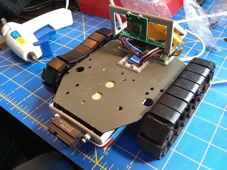
This picture doesn't include the USB power bank I'm using to power the Raspberry Pi. The AA's on the bottom are just to power the motors (6V). I could buck the voltage down and run it all off those batteries, but I'm not planning to perfect this robot. Instead, I'd rather scale up!
I'm able to get distance sensor and camera data over Wifi, and even devised a way to control the tank over gamepad. With the hardware working, what's lacking is software, and automation in far greater measure than I'm using here is possible.